Xor Logic Gate
For 3 input XOR gate and XNOR gate by solving the equations I got the result as in the picture. A general idea of a symbol for a XOR Logic Gate.

File Xor Ansi Svg Wikimedia Commons
Tutorial 2 Creating An Xor Circuit

Xor Gate Wikipedia
A b out 0 0 0 0 1 1 1 0 1 1 1 0 the xor a and not b or not a and b which is beginsplitoverlineABAoverlineBendsplit.

Xor logic gate. One element conspicuously missing from the set of Boolean operations is that of Exclusive-OR often represented as XOR. Lets first break down the XOR function into its AND and OR counterparts. Drive XOR gate from NAND gateusing digital logic.
This is the reason an XOR gate is also called an. An XOR gate implements an exclusive or from mathematical logic. The 2d XOR problem Attempt 2.
I mean intuitively to me I should get this one if I do it step by step followed by the definition xor a and. Number of phase possible 2 n 2 2 4. The AND gate has a flat input side and round output side.
When you connect multiple gates together you have a combined logic system or combinatorial logic. The Boolean expression for a logic NAND gate is denoted by a single dot or full stop symbol. This gate produces the reverse output of applied input.
The truth table of a NOT gate can be represented as. Xor gate now I need to construct this gate using only 4 nand gate. NOT gate has only one input and one output.
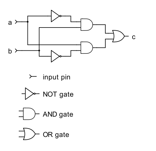
A common example is a simple logic gate. A gate is defined as a logic device which computes functionally on a 2 valued input signal. Another equivalent circuit for the Exclusive-OR gate uses a strategy of two AND gates with inverters set up to generate high.
In electronics and logic an XOR gate with more than 2 inputs is commonly regarded as a cascade of 2-input XOR-gates thus behaving as a parity-checker with the output being on if there is an odd number of inputs turned on. This logic gate works like this. Most logic gates take an input of two binary values and output a single value of a 1 or 0.
This logic gate consists of two input terminal and one output terminal. Other logic gates include AND gates OR gates NAND gates NOR gates XOR gates XNOR gates. However when both inputs are high 1 the NAND gate outputs a low 0 logic level which forces the final AND gate to produce a low 0 output.
Logic gates perform basic logical functions and are the fundamental building blocks of digital integrated circuits. The Exclusive-OR or Ex-OR gate is a digital logic gate with more than two inputs and gives only one output. Combinatorial logic is a concept in which two or more input states define one or more output states where the resulting state or states are related by defined rules that are independent of previous states.
XOR gate sometimes EOR or EXOR and pronounced as Exclusive OR is a digital logic gate that gives a true 1 or HIGH output when the number of true inputs is odd. NOT Gate Transistor Circuit Diagram. We know that the imitating the XOR function would require a non-linear decision boundary.
NAND gate is called a universal gate since the AND gate OR gate and NOT gates can be realised using this gate. Among these all gates have two inputs and one output except NOT gate. The logic gate performs this modulo sum operation without including carry is known as XOR gate.
Apart from its importance in understanding mathematical reasoning logic has numerous applications in Computer Science varying from design of digital circuits to the construction of computer programs and verification of. The transistor circuit diagram of a NOT gate also known as a transistor inverter is shown. Any above it are ignored.
Other Logic Gates XOR Gate. An XOR gate is normally two inputs logic gate where the output is only logical 1 when only one input is logical 1. The exclusive or gate symbol is just like the OR gate but it has an additonal curved line crossing the inputs.
However only logic gate lamps below the lowest faulty lamp in the chain affect the chance of the logic gate emitting a signal. The rules of logic give precise meaning to mathematical statements. These rules are used to distinguish between valid and invalid mathematical arguments.
Below is an image which shows the graphical symbols and truth tables associated with. In the case if any of the input has binary zero then the output we got will be binary 0. V s will initially charge up quickly but the tail end of the transient is slow.
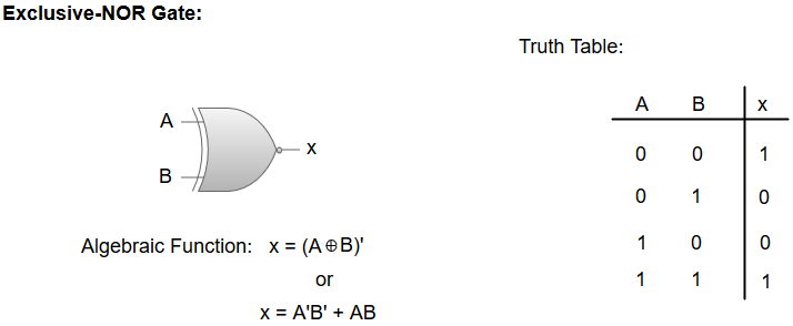
-The XNOR gate negated XOR gives an output of 1 both inputs are same and 0 if both are different. Exclusive OR XOR gate. What Is an XOR Gate.
An XOR gate sometimes referred to by its extended name Exclusive OR gate is a digital logic gate with two or more inputs and one output that performs exclusive disjunctionThe output of an XOR gate is true only when exactly one of its inputs is trueIf both of an XOR gates inputs are false or if both of its inputs are true then the output of the XOR gate is false. Popular Interview question on internet. A logic gate is an idealized model of computation or physical electronic device implementing a Boolean function a logical operation performed on one or more binary inputs that produces a single binary output.
For the case of even number of inputs XOR and XNOR are complement to each other. This solution holds good when number of inputs to the gates are odd. An XNOR gate sometimes referred to by its extended name Exclusive NOR gate is a digital logic gate with two or more inputs and one output that performs logical equalityThe output of an XNOR gate is true when all of its inputs are true or when all of its inputs are falseIf some of its inputs are true and others are false then the output of the XNOR gate is false.
If both inputs are the same the output will be off. XOR from NAND logic NAND to XOR conversion equations circuit minimizatio Truth tables. The output of a XOR gate will be true only if the two inputs are different from each other.
Digital design entry level interview questions for asic fpga verification. Every Logic gate has a graphical representation or symbol associated with it. But why do we have to stick with a single decision boundary.
That is a true output results if one and only one of the inputs to the gate is trueIf both inputs are false 0LOW or both are true a false output results. Welcome to XOR exclusive OR which solves this problem much in line with standard human reasoning. 0 0 0 0 1 1 1 0 1 1 1 0 The input and output are the same as our OR gate but this time the input really does need to be exclusiveIf the input is true and true the output is false.
The XOR function on two boolean variables A and B is defined as. I know the answer but how to get the gate diagram from the formula. EE141 4 NMOS-Only Logic 00 0 05 1 15 2 10 20 30 Time ns V o l t a g e V s Out In V s is initially 0.
Logic gates are of many types such as OR AND NOR NAND EX OR and NOT etc. A NOT gate can easily be realized by using a simple bipolar transistor. The current drive of the transistor gate-to-source voltage is reduce significantly as V.
Logic 0 low or logic 1 high. XOR exclusive or gates have two inputs. There are seven.
When both inputs are equal either are 1 or both are 0 the output will be logical 0. Depending on the context the term may refer to an ideal logic gate one that has for instance zero rise time and unlimited fan-out or it may refer to a non-ideal physical device see. The logic or Boolean expression given for a logic NAND gate is that for Logical Addition which is the opposite to the AND gate and which it performs on the complements of the inputs.
Some circuits may have only a few logic gates while others such as microprocessors may have millions of them. The working of these gate is such that at output terminal we will get binary 1 if and only if both the input are binary 1. So according to the solution the outputs of the 3 input XOR and XNOR gates are same.
Each of the inputs and outputs can attain either of two states. Whereas the OR function is equivalent to Boolean addition the AND function to Boolean multiplication and the NOT function inverter to Boolean complementation there is no direct Boolean equivalent for Exclusive-OR.

Lesson Worksheet Xor Gates Nagwa
Xor Gate Wikipedia

How Logic Gates Work Or And Xor Nor Nand Xnor And Not Cloudsavvy It

Reconfigurable All Optical Not Xor And Nor Logic Gates Based On Two Dimensional Photonic Crystals Sciencedirect

How Logic Gates Work In Digital Electronics Eagle Blog

The Exclusive Or Function The Xor Gate Boolean Algebra Electronics Textbook

Exclusive Or Xor Gate Logic Gate And Gate Xnor Gate Binary Number System Angle Text Rectangle Png Pngwing
Logic Gates Computer Organization And Architecture Tutorial Javatpoint


